
1000Tons Compression and Shear Testing Machine
Ⅰ.Introduction
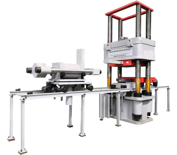
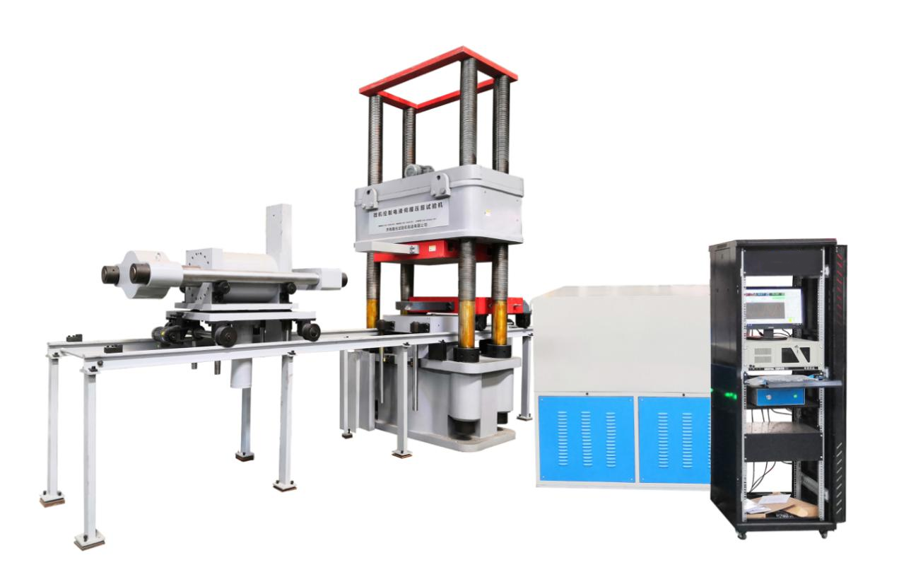
YJW-10000 microcomputer-controlled electro-hydraulic servo compression and shear testing machine with oil cylinder down type, four-column structure, high frame stiffness strength, small deformation, to meet the highway, railroad bridge plate, basin, spherical bearing testing requirements, the test space is steplessly adjustable, convenient for different heights of test requirements. Adopt self-developed proprietary multi-channel closed-loop coordinated loading electro-hydraulic servo control system, microcomputer control coordinated multi-stage hydraulic loading, continuous loading smoothly, multi-stage test force maintenance, automatic data collection and storage, drawing curves, automatic printing of test reports, computer timely control of the test process, display test force and test curve, simple and reliable operation.
Ⅱ.Test items
This machine is used to test the finished mechanical properties of highway bridge rubber bearing test. Can be carried out separately.
1 plate type bearing
Compressive elastic modulus test
Ultimate compressive strength test
Shear modulus of elasticity test
Shear bonding performance test
Shear aging test (need to add aging box, the cost is negotiable)
Friction coefficient test
Allowable corner test
2 Basin type bearing
Finished bearing vertical bearing capacity test
Finished bearing friction coefficient test
Finished bearing rotation test
3 Spherical steel bearing
Finished bearing vertical bearing capacity test
Friction factor test of finished bearing
Determination of rotating moment of finished bearing
Ⅲ.Product technical performance characteristics
1.Host pendant system
1.1 Adopt under-mounted plunger cylinder and four-screw frame type mainframe, the test space is steplessly adjustable, which is convenient for the test demand of different heights. The whole machine has high rigidity, small deformation, and accurate measurement data.
1.2 The base and crossbeam adopt the overall casting structure, and its structure has reasonable distribution of cloth tendons, large rigidity of workpiece, beautiful and generous appearance, which ensures the safety and reliability of the whole parts.
1.3 The beam is movable, can realize the stepless adjustment of the test space, in addition to meet the test of rubber support, increase the corresponding auxiliary tools, but also can do some larger specimens of compression test.
1.4 The screw is made of 45# high quality structural steel and the filament is high grade ductile iron, which not only meets the strength but also improves the reliability of the filament of the screw, the filament of the screw is processed by high precision machine tools and heat treated by aging, tempering and shaping to ensure the accuracy of the workpiece.
1.5 The cylinder is plunger type structure, and processed by high precision machine tools to ensure accuracy, the final process of the cylinder bore is precision machining by honing machine, thus reducing the friction of the cylinder piston and improving the measurement accuracy and service life of the testing machine; the piston is a whole entity, and the diameter is large to ensure its high pressure rod stability and better rigidity, the piston rises with oil pressure to push, and falls by its own weight to fall.
1.6 The cylinder adopts advanced compound sealing technology, using imported seals, and has two levels of sealing with gap oil film and Sturgeon, and after the two levels of sealing, set the gap return oil receiver to return to the oil tank. This sealing method ensures the reliability of cylinder sealing, improves the accuracy and stability of force measurement, and increases the service life of cylinder and piston.
1.7 The upper and lower pressure plate are integral, the flatness is better, to ensure the accuracy and reliability of the rubber bearing test results.
1.8 The crossbeam lifting transmission system adopts the way of spiral vice composed of screw filaments to lift. The motor drives the sprocket and chain, and the chain drives the screw vice drive to realize the stepless adjustment of the test space. Four screw two left-hand rotation, two right-hand rotation, characterized by the elimination of the beam lifting on the screw starting torque.
1.9 Feeding trolley and shear device trolley share a common rail, and flush with the ground, easy and fast loading and unloading of specimens, laboratory height requirements reduced.
1.10 A 200mm thick table is installed between the feeding trolley (i.e. lower platen) and the main cylinder piston, which increases the force strength of the lower platen. A guiding column is installed on the table to avoid the rotation of the piston during the test, which makes the test force value more accurate.
2.Transverse shear system
2.1 The shearing system consists of shearing cylinders, front and rear beams, pulling bars on both sides, shearing middle drawer, upper and lower friction plates, top block, connecting pins, shearing trolley, etc. The use of double-action servo cylinder to apply test force, supported by the shear trolley, floating cylinder to adjust the vertical height of the transverse shear, shear trolley electric walking device with electromagnetic clutch, adjust the front and rear position of the shear device. Shear trolley lift to adjust the horizontal position of the loading device to ensure the accuracy of the shear force value and improve the detection accuracy.
2.2 double-action servo cylinder, connecting pull bar, friction plate, shear trolley, floating cylinder and guide rail constitute the transverse main system.
2.3 The shear trolley is composed of rollers, floating cylinders, guiding columns, walking motors and clutching devices.
2.4 shear trolley forward and backward electrically to achieve, without manual propulsion, and equipped with electromagnetic clutch. Walking clutch with electric suction, after the start of the shear test, clutch power loss release. Test trolley will follow the shear deformation of the rubber bearing to move, at this time the need to move the trolley resistance to a minimum, that is, when moving without the constraints of the walking motor, so that the results of the shear test more accurate.
2.5 shear loading device vertical height by the shear trolley carrying the floating cylinder to adjust the floating cylinder can adjust the shear cylinder vertical height to ensure that the axis of the load sensor and the middle shear draw plate symmetry axis coincide to ensure the accuracy of the specimen horizontal axial force.
2.6 shear cylinder for a single rod double-acting servo cylinder, the use of imported Glacier ring, seal and dust ring seal, good sealing, long service life, high safety factor.
2.7 shear force value using high-precision load sensor direct force measurement, precision 0.3 level, range 600kN, can withstand large overload load, long service life.
2.8 using two grating type displacement sensor to measure the shear deformation of the rubber bearing, sensor top rod and the middle contact with the extraction plate, distributed in the two ends of the extraction plate, accurate measurement of rubber bearing shear deformation.
2.9 Equipped with two stainless steel plates, good flatness and finish, to meet the requirements of the friction coefficient test.
3. Corner system
3.1 The corner system adopts double-acting servo cylinder to apply force, and is fixed on the base of the vertical host.
3.2 The double-acting servo cylinder, corner plate, spherical rod and support base constitute the cornering main system.
3.3 The corner cylinder is a single-outlet rod double-acting servo cylinder, sealed with imported Glacis ring, Stirrup seal and dust ring, etc., with good sealing, long service life and high safety factor.
3.4 The corner force value is measured directly by high precision load sensor, with accuracy 0.3 level and range 1000kN, which can withstand large overload load and long service life.
3.5 Use four grating type displacement sensor to measure the corner deformation of the rubber bearing.
3.6 Between the load sensor and the corner plate, there is a ball hinge device composed of ball head ball seat, which can be freely centered to ensure the accuracy of the corner vertical force.
3.7 According to different sizes of specimens, the length of the spherical rod attachment can be changed to meet the test requirements of different specimen thickness.
4. Hydraulic system
This system is a load-adapted oil-feed throttling speed regulation system. The hydraulic oil in the tank enters the oil circuit through the motor driven high pressure oil pump, flows through the check valve, high pressure oil filter, servo valve and enters the cylinder. The high precision load sensor is installed on the piston of the cylinder, which converts the force signal into electrical signal and transmits it to the computer, which collects and processes it and then converts it into the test force value and displays it. The servo control can realize equal speed test force (stress), equal speed displacement, test force (stress) hold, displacement hold, etc.
Load-adapted oil inlet throttling speed control system automatically controls the opening of the valve according to the size of the test force, which reduces heat generation, reduces excess energy loss and reduces the motor load power.
In order to reduce system heat and save energy, the servo cylinder uses servo valve and differential pressure valve to implement control of flow, direction and test force respectively. When conducting the test, the size of the electro-hydraulic servo valve opening directly control the piston in and out, so as to achieve the speed of the test, the pressure of the differential pressure valve is automatically adjusted according to the size of the test force. This way of using differential pressure valve control is called load-adapted control, this control mode is when the hydraulic system pressure rises and falls, the differential pressure valve adjustment pressure changes, and the system pressure to maintain synchronization, this control mode not only greatly reduces energy consumption, reduce the heat, reduce the pressure of the cooling system, and improve the safety and reliability of the entire hydraulic system.
The cooling system adopts water-cooling mode. Water-cooled cooling effect is good, and belongs to the quiet cooling mode, quiet, no impact on the test environment, to ensure the accuracy of the test results.
5. Electrical part
The electrical system adopts an integrated control cabinet, and the operation console adopts a desktop structure, which is arranged in the test operation area, and the specially designed operation panel makes all kinds of test operations clear at a glance. This control cabinet integrates computer, monitor, keyboard, mouse, printer and strong power control operating system into one, which is simple and clear and easy to use.
The operation buttons are controlled by 24V weak power, which ensures the safety of operators.
The main electrical components adopt ABB and other famous brands, with stable performance and reliable quality.
Separate design of strong and weak electric power, so that the strong electric part is far away from the operator.
The functions such as front and rear limit protection of the cylinder piston are realized through the electrical port.
Ⅲ.Main technical indicators and parameters
1 Vertical loading system
1.1 Maximum test force: 10000kN.
1.2 Test force measurement range: 2% to 100% F.S.
1.3 Test force measurement accuracy: ≤ ±1%.
1.4 maximum speed of the cylinder at no load: 40mm/min.
1.5 Maximum stroke of the cylinder: 300mm.
1.6 displacement measurement range: 0~300mm.
1.7 Displacement measurement accuracy: ≤±1% F.S.
1.8 Deformation measurement index value (mm): 0.001 (vertical deformation), 0.001 (radial deformation).
1.9 deformation measurement: four grating type digital displacement sensors measure the vertical deformation of the specimen.
Four grating type digital displacement transducer to measure the radial deformation of the specimen.
Deformation measurement range: 0~50mm (vertical deformation), 0~20mm (radial deformation).
1.10 test adjustment space: 0~1000mm.
1.11 test maximum space: 1000mm.
1.12 Size of upper platen: 1050mm × 1050 mm × 200mm.
1.13 trolley platen size: 1050mm × 1050 mm × 200mm.
1.14 isochronous test force control range: 0.5kN/s~25kN/s.
1.15 Equivalent displacement control range: 0.5 mm /min~50 mm /min.
2.Transverse shear system
2.1 maximum test force: 2000kN.
2.2 test force measurement range: 2%-100% F.S.
2.3 accuracy of the test force: ≤ ±1%.
2.4 Maximum stroke of the cylinder: 250mm.
2.5 Maximum speed of the cylinder at no load: 50mm/min.
2.6 Displacement measurement range: 0~250mm.
2.7 Displacement measurement accuracy: ≤±1%F.S.
2.8 Deformation measurement index value (mm): 0.001.
2.9 deformation measurement: two grating type digital displacement sensors to measure the transverse shear deformation of the specimen.
2.10 deformation measurement range: 0~100mm
2.11 deformation measurement accuracy: ≤ ± 1% F.S.
3.Corner system
3.1 Maximum corner ejection force: 600kN.
3.2 Test force measurement range: 2%-100% F.S.
3.3 Accuracy of test force: ≤ ±1%.
3.4 Maximum stroke of the cylinder: 150mm.
3.5 Maximum speed of the cylinder at no load: 0-60mm/min.
3.6 Displacement measurement range: 0~300mm.
3.7 Displacement measurement accuracy: ≤±1% F.S.
3.8 deformation measurement range: 0~50mm (with four sensors in vertical direction)
3.9 Deformation measurement index value: 0.001mm.
3.10 Deformation measurement accuracy: ≤ ±1% F.S.


