What is the tensile testing?
Tensile testing refers to a test method for determining the properties of a material under an axial tensile load. Using the data obtained from the tensile test, the elastic limit, elongation, elastic modulus, proportional limit, area reduction, tensile strength, yield point, yield strength and other tensile properties of the material can be determined. Creep data can be obtained from tensile tests conducted at elevated temperatures. The procedure for tensile testing of metals can be found in the ASTM E-8 standard. Methods for tensile testing of plastics are described in ASTM D-638, D-2289 (high strain rate), and D-882 (sheet). ASTM D-2343 standard specifies the tensile test method applicable to glass fibers; ASTM D-897 standard specifies the tensile test method applicable to adhesives; ASTM D-412 standard specifies the tensile test for hard rubber method.
ensile tests can determine a series of strength and plasticity indexes of materials. Strength usually refers to the ability of a material to resist elastic deformation, plastic deformation and fracture under the action of external force. When a material is subjected to a tensile load, the phenomenon that the material continues to undergo significant plastic deformation when the load does not increase is called yielding. The stress when yielding is called the yield point or the physical yield strength, expressed by σS (Pa). In engineering, there are many materials without obvious yield point. Usually, the stress value when the residual plastic deformation of the material is 0.2% is used as the yield strength, which is called the conditional yield limit or the conditional yield strength, and is expressed by σ0.2. The maximum stress value reached by a material before fracture is called tensile strength or strength limit, and is represented by σb (Pa).
Plasticity refers to the ability of metal materials to plastically deform under load without damage. The commonly used plasticity indicators are elongation and section shrinkage. Elongation, also known as elongation, refers to the percentage of the ratio of the total elongation to the original length after the material sample is broken by a tensile load, expressed by δ. The area shrinkage rate refers to the percentage of the ratio of the area of the material sample to the original cross-sectional area after the material sample is broken by the tensile load, expressed by ψ.
Conditional yield limit σ0.2, strength limit σb, elongation δ and area shrinkage ψ are four performance indicators that are often measured in tensile tests. In addition, the elastic modulus E, proportional limit σp, elastic limit σe, etc. of the material can also be determined.
Test methods Tensile tests are carried out on a material testing machine. There are mechanical, hydraulic, electro-hydraulic or electronic servo-type testing machines. Specimen type can be full cross-section of material, and can also be processed into circular or rectangular standard specimens. Some physical samples such as steel bars and wires generally do not need to be processed and keep their full cross-sections for testing. During the preparation of the sample, the influence of cold and hot processing on the material structure should be avoided, and a certain degree of smoothness should be guaranteed.
During the test, the testing machine uniformly stretches the sample at a specified rate, and the testing machine can automatically draw a tensile curve. For materials with good plasticity such as low carbon steel, when the sample is stretched to the yield point, the force measuring pointer has obvious jitter, and the upper and lower yield points (and) can be separated. When calculating, the δ and δ of the material are often taken. ψ can be calculated by splicing the specimens after test fracture, measuring their elongation and section reduction.
Low carbon steel tensile test
1. Prepare the test piece. Use a marking machine to scribe a circular line within the original gauge range (or punch small punch points with small steel), and divide the gauge length into 10 equal-length grids. Use vernier calipers to measure the diameter of the specimen at both ends and two mutually perpendicular directions in the middle of the original gauge length of the specimen, and take the arithmetic mean value as the diameter of the section at that location, and then select the minimum value of the three section diameters to calculate The original cross-sectional area A of the specimen. (take three significant figures).
2. Adjust the testing machine. According to the tensile strength σb of the low carbon steel and the original cross-sectional area, the maximum load of the specimen is estimated, the corresponding pendulum is configured, and the appropriate force measuring plate is selected. Start the testing machine and raise the worktable by about 10mm to eliminate the influence of the self-weight of the worktable system. Adjust the active pointer to align with the zero point, the driven pointer and the active pointer are close to each other, and adjust the automatic drawing device.
3. Clamp the specimen. First clamp the specimen in the upper chuck, then move the lower chuck to a suitable clamping position, and finally clamp the lower end of the specimen.
4. Inspection and test drive. Ask the experiment instructor to check the completion of the above steps. Start the testing machine, preload a small amount of load (the stress corresponding to the load cannot exceed the proportional limit of the material), and then unload to zero to check whether the testing machine works normally.
5. Carry out the test. Start the testing machine, load slowly and evenly, and carefully observe the rotation of the force measuring pointer and the drawing of the graph by the drawing device. Pay attention to capture the yield load value and record it to calculate the stress value σS at the yield point. Pay attention to the slip phenomenon during the yield stage. After the yield phase, the loading speed can be faster. When it is about to reach the maximum value, pay attention to observe the phenomenon of "neck". Stop immediately after the specimen is broken, and record the maximum load value.
6. Remove the test piece and recording paper.
7. Use a vernier caliper to measure the gauge length after the break.
8. Use a vernier caliper to measure the minimum diameter d1 at the neck down.
Cast iron tensile test
1. Prepare the test piece. Except that there is no need to score lines or hit small punch points, the rest are the same as low carbon steel.
2. Adjust the testing machine and automatic drawing device, install the test piece, and check the above work (the same steps as the low carbon steel tensile test).
3. Conduct an experiment. Start the testing machine and load slowly and evenly until the specimen is pulled off. Turn off the testing machine, record the maximum load value at break, and remove the specimen and recording paper.
(4) End the experiment.
Ask the instructor to check the test records. Restore the test equipment and tools, and clean up the test site. Finally, organize the data and complete the test report.
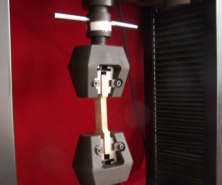
Tensile fixture
The tensile fixture itself is a locking mechanism. There is no fixed mode in the structure, and the structure varies greatly according to different samples and the size of the test force. The sample with large test force generally adopts the inclined plane clamping structure, and the clamping force increases with the increase of the test force. , the shoulder sample adopts a suspension structure, etc. If the fixtures are divided by structure, they can be divided into wedge-shaped fixtures (referring to the clamps using the inclined surface locking principle structure), and clip-type fixtures (referring to the principle of single-sided or double-sided screw topping) Structure fixture), winding fixture (referring to the fixture that the sample is locked by winding method), eccentric fixture (fixture with eccentric locking principle structure), lever fixture (referring to the fixture with lever force amplification principle structure) , Shoulder clamps (refer to the clamps suitable for shoulder samples), bolt clamps (refer to the clamps suitable for testing thread strength of bolts, screws, studs, etc.), 90° peel clamps (refer to the two samples suitable for jig for pendant, straight peel) etc. We know that the mechanical locking structures are: thread (ie thread, screw, nut), bevel, eccentric, lever, etc. The fixture is the combination of these structures. The structures of these fixtures have their own advantages and disadvantages, for example: wedge-shaped Fixtures, the initial clamping force is small and increases with the test force. The clamping force increases accordingly. For the clamping fixture, the initial clamping force is large and increases with the test force. The clamping force is reduced accordingly.
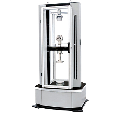
Tensile testing machine
Tensile testing machine is also called material tensile testing machine and universal material testing machine. It is a new generation of mechanical testing equipment that integrates computer control, automatic measurement, data acquisition, screen display and test result processing.